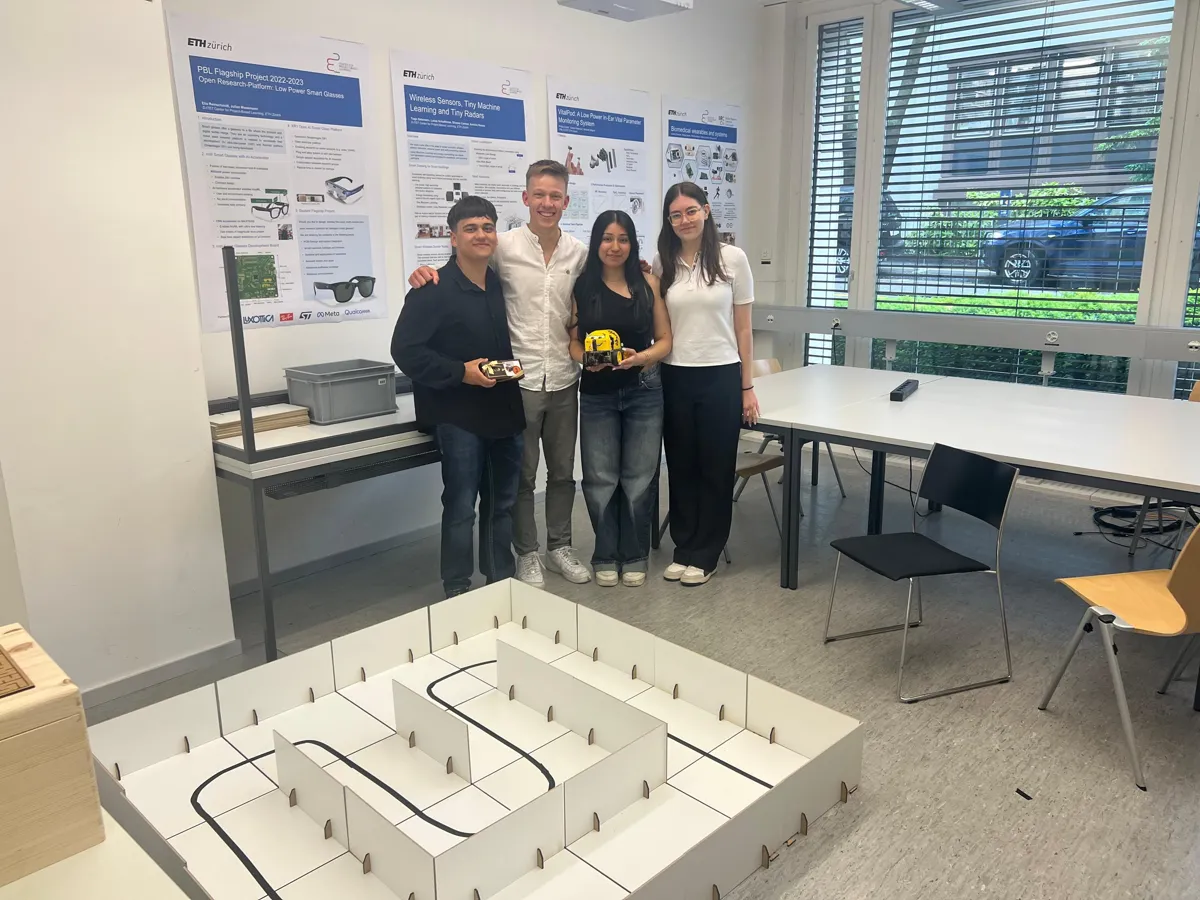
Line-Following and Maze Robot
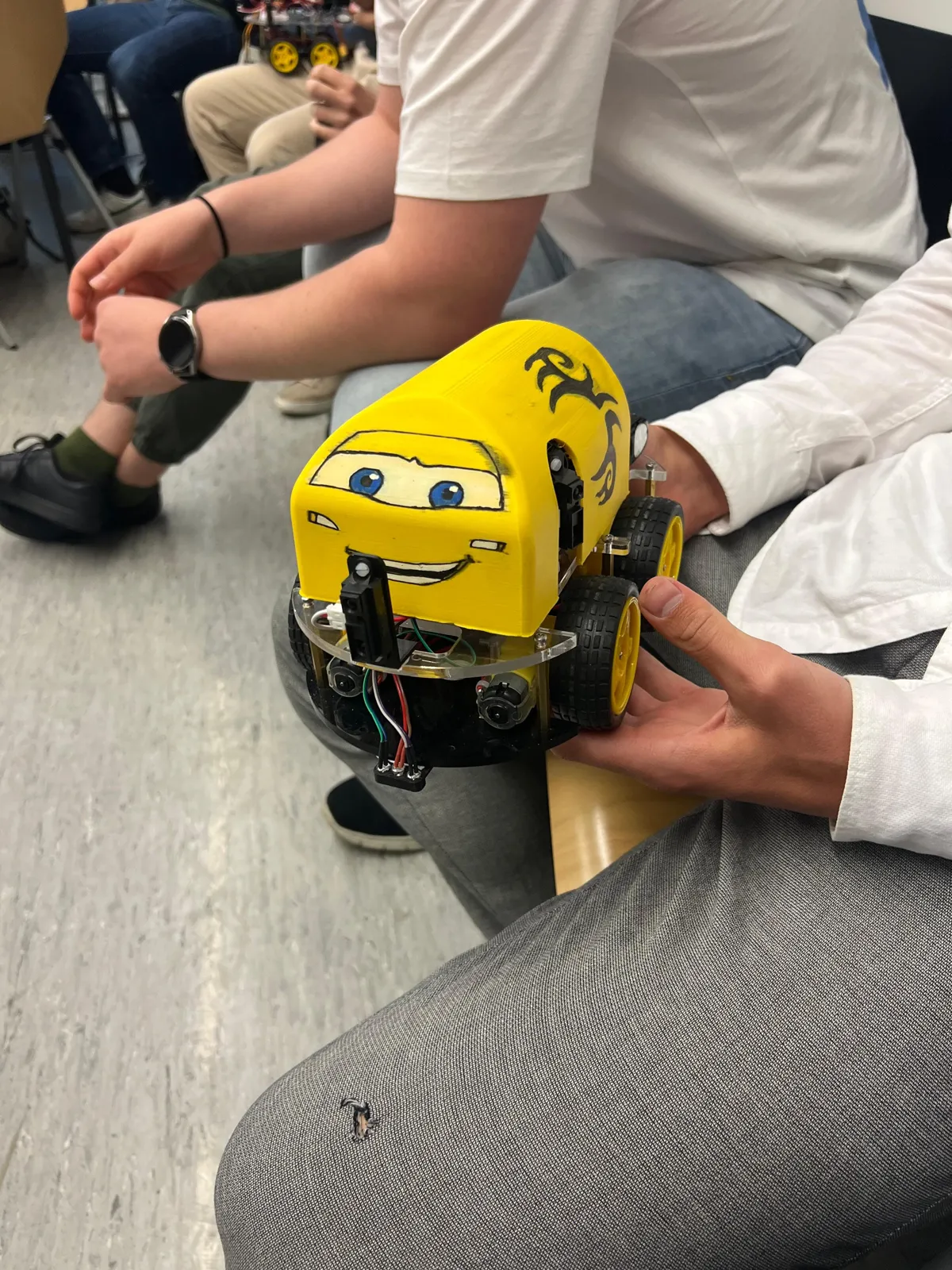
A four-wheel robot that follows a line as fast as I could make it go, then solves a maze along the left wall.
- Context
- Exploration Project, D-ITET, ETH Zürich
- Team size
- 3, this page covers only my parts
- Built with
- STM32 in C, STM32CubeIDE
- Status
- Completed
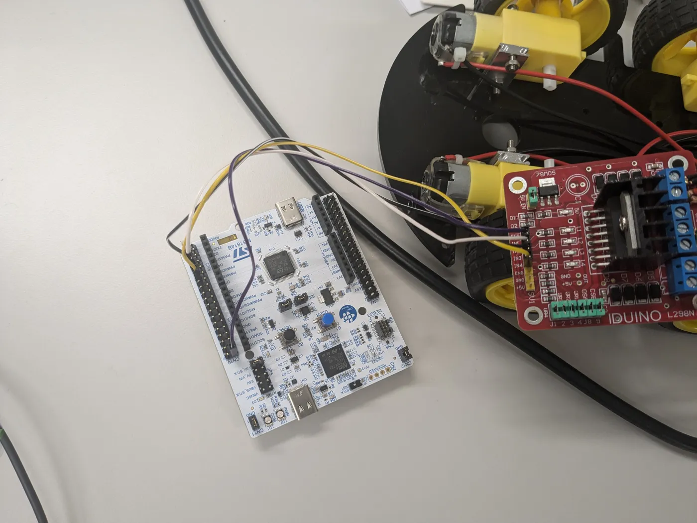
Four wheels, left and right pair coupled, so it steers on the PWM duty cycle of each side. Goal: maximum speed without losing the line.
Key decision: a calm controller plus a state machine
One controller for the whole track meant choosing between two bad options — a high proportional gain that gets round the corners but oscillates everywhere else, or a lower speed, which defeats the point.
So I split it. A conservative PD controller drives the ~90% of the track where stability matters, and a state machine takes the tight corners and the lost-line cases — doing the high gain's job without its oscillation.
Sensing
- Line: a photodiode and op-amp into an ADC channel. A fixed threshold drifted — LED intensity falls with the battery, and the photodiodes were not mounted rigidly — so I wrote a calibration routine that measures the thresholds instead of assuming them.
- Maze: left-wall following with a PD controller on three distance sensors, front, left and right. Distance sensors, not LiDAR.
A rigid sensor mount would have removed the need for the calibration routine instead of compensating for it.
The build