Ball-on-Plate Control Demonstrator
A motorised two-axis plate balances a real ball on a screen. A camera tracks the ball's position. The ball interacts with arcade-style games for a playful visualization of control theory
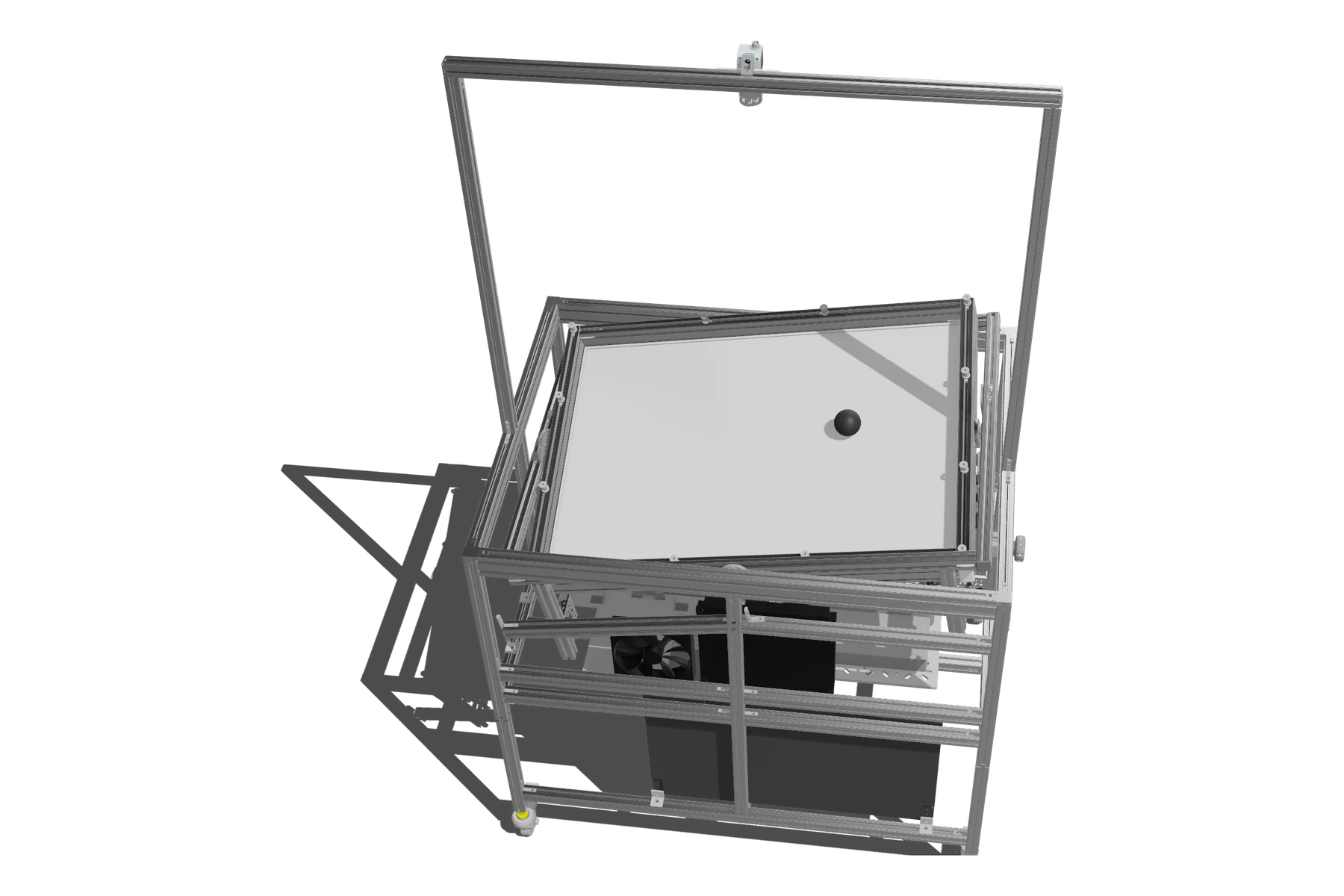
- Now
- Bachelor's thesis: Full hardware redesign, since September 2026
- Before
- Semester project: Controllers and demos, autumn 2025
- Context
- Automatic Control Lab, D-ITET, ETH Zürich
- Team size
- Solo, with supervisor guidance
How it works
DC-motors in combintation with encoders form an inner control loop to set the plate angles.
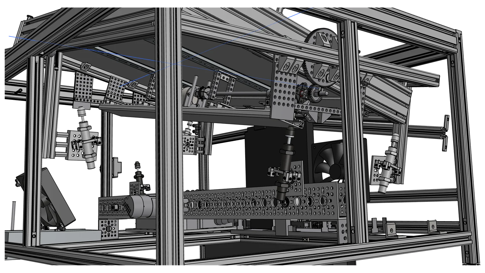
What I do - Bachelor's Thesis
I completely redesign the old system. Major changes include:
- new screen with new format: 3:2 instead of 16:18
- new, improved mechanics: belt instead of gear for the torque-heavy axis
- adapted and improved software to fit the new format
Challenges
Main challenge is the belt design: Its nonlinear dynamics make it very important to place it optimally.
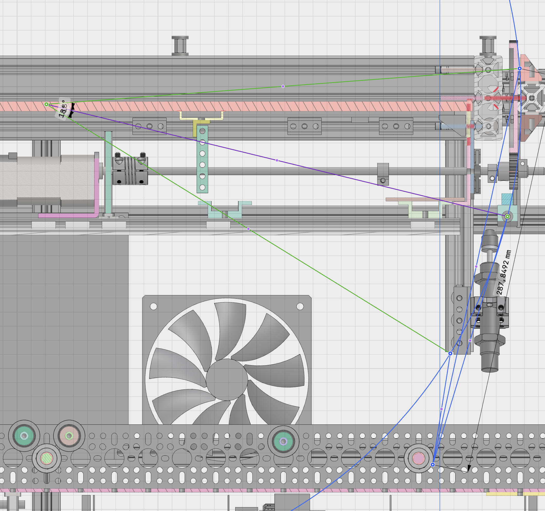
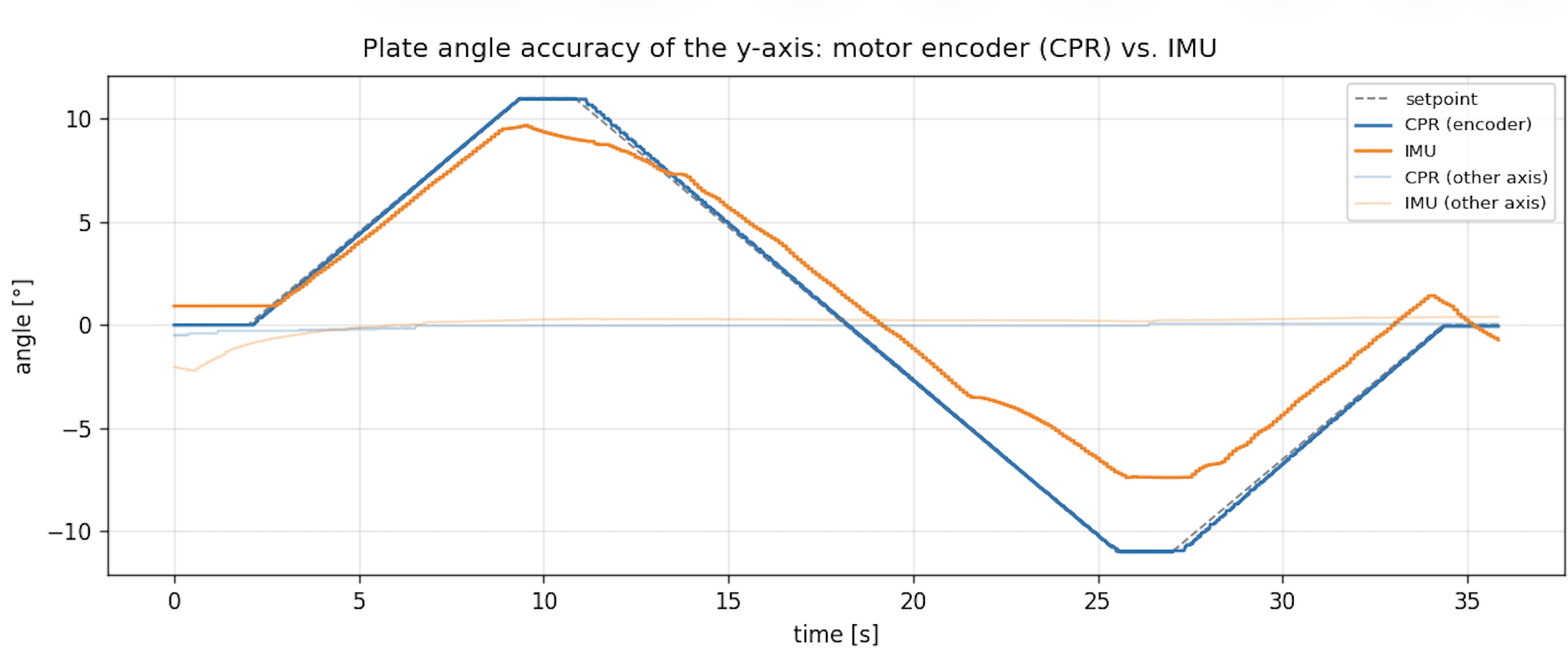
On both axes, the inertia and linear forces on mounting parts must be minimized to enable best possible control. On the old system, I found indicators for suspected gear slip or loose, bending parts. IMU data deviated strongly from encoder data. This must not happen on the new system.
What's next
CAD is finished, parts are ordered and on their way. Next up is structural assembly, wiring and setup of the Raspberry Pi and its GPIO channels. Then comes tuning the inner loop, adapting the software and (possibly, as a stretch goal) a new camera system which is mounted on the plate-frame
Controllers, Games and Demos - Semester Project 2025
- PID and LQR for the outer control loop.
- Live-tuning: Both controllers are modifiable while the games run, so that users can witness the effects of each parameter interactively
- Three games: a generated racing track, a Flappy Ball PID visualiser, rectangle tracking.
Racing Track
Racing Track is the best example to showcase the art of control to students: It is incredibly difficult to stay on the track and score laps while steering the plate manually. However, the automatic controller can manage very well! You can see the PID in action in simulation.
An implementation I'm particularly proud of is the random track generation: Racing Track is a class consisting of 4 corner elements with random placement on the map. After generating the corner elements, connecting elements made of tanh-functions are generated.
The most counterintuitive part about PID is the Integral Control. My supervisors had the idea of showcasing integral control using a 1D- control situation, and colormarking the area between actual trajectory and reference trajectory. I implemented this visualization in the "Flappy Ball" - game.